Single mode vs multimode fiber comes down to reach, the installed cable, and the optics at both ends. Single-mode fiber suits longer links; multimode fiber suits supported short links, often using cable already installed in a building.
The cheapest cable can still produce the costlier link. Replacing a working cable route, changing patch panels, and testing new connections can outweigh a saving on transceivers. If you manage a network refresh, the useful question is which complete system meets your next requirement.
This guide compares single mode vs multimode fiber through actual Cisco 10G and 100G examples. You’ll see why an OM3 channel that supports one speed may fall short with a different optic. You’ll also learn what OM4 and OS2 labels tell you, which details they leave open, and how to price a complete connection.
Start with the cable records you have today. Then compare the required speed, routed length, connectors, and measured loss against the exact module data sheets. The tables and six-step worksheet below turn that process into a parts list you can discuss with your installer and equipment supplier.
Key Takeaways
- Single-mode fiber carries one spatial propagation mode; multimode fiber carries several, which can limit reach through modal dispersion.
- Cisco SFP-10G-SR reaches up to 300 m on OM3 and 400 m on OM4; its 100G SR4 example has shorter limits.
- OS2, connector shape, and jacket color alone do not establish a supported optical link.
- Compare both optics, the complete cable channel, installation, testing, and spares when you price the system.
Single mode vs multimode fiber: key differences
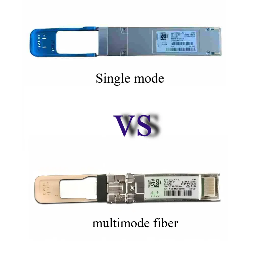
What the core and propagation mode change
A mode describes how light travels through the fiber. Single-mode fiber (SMF) supports one spatial mode at its operating wavelength. Multimode fiber (MMF) supports multiple modes, which can arrive at different times and spread a light pulse.
That spreading is called modal dispersion. It helps explain the reach limits in a single mode vs multimode fiber comparison. Multiple modes are not separate data channels, and a single spatial mode does not mean the system must use only one wavelength.
EXFO’s fiber comparison describes the common size difference as roughly 9 micrometers for SMF versus 50 or 62.5 micrometers for MMF. These are introductory size descriptions; the actual fiber specification controls its geometry.
| Attribute | Single-mode fiber | Multimode fiber |
|---|---|---|
| Common cabling categories | OS1 and OS2 | OM1 through OM5 |
| Light propagation | One spatial mode | Multiple spatial modes |
| Typical wavelengths | 1310 or 1550 nm | 850 or 1300 nm |
| Common planning role | Longer routes and suitable short links | Supported shorter building or data center links |
| Main purchase check | Exact optic, fiber specification, and loss | Exact optic, grade, bandwidth, and loss |
Typical wavelengths are examples, not exclusive rules. Modern short-reach MMF links often use vertical-cavity surface-emitting lasers (VCSELs), so “multimode uses LEDs” is an unsafe blanket statement.
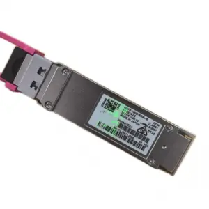
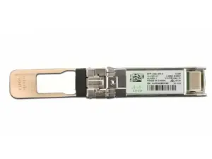
When comparing single mode vs multimode fiber, keep the module separate from the cable. Browse Cisco optical modules to identify candidate part numbers, then check each against your endpoints and cable records. A catalog entry alone does not confirm stock or platform support.
Understand OS2, OM3, and OM4 cabling
Read the grade from the cable and test record
Single mode vs multimode fiber is the first distinction; the cabling grade is the next. OM3 and OM4 are laser-optimized multimode categories. OS2 is a single-mode cabling category, rather than a speed setting or a transceiver type.
The FOA fiber nomenclature reference separates these categories and fiber sizes. Use the printed cable legend, installation records, and test reports to identify the entire channel, including patch cords.
| Category | Fiber description | What to establish before reuse |
|---|---|---|
| OM1 | 62.5/125 micrometer multimode | Whether the selected optic supports this legacy grade |
| OM2 | 50/125 micrometer multimode | Its supported application and reach |
| OM3 | 50/125 micrometer laser-optimized multimode | Application-specific bandwidth and channel length |
| OM4 | 50/125 micrometer laser-optimized multimode | Whether its supported reach meets the actual route |
| OM5 | Wideband multimode | Whether the application uses its wavelength capability |
| OS1 / OS2 | Single-mode cabling categories | Fiber specification, construction, and channel loss |
For single mode vs multimode fiber identification, color is a clue. Common premises conventions include aqua for OM3 or OM4, yellow for SMF, and lime green for OM5. Outdoor jackets and custom colors can differ, so color cannot replace the label or records.
An OS2 label also does not prove that a channel meets every optic’s fiber and loss requirements. Avoid reducing OS1 and OS2 to an absolute indoor-versus-outdoor rule; select the cable construction for the actual route and environment.
If an OM3 trunk has unidentified patch cords, document those cords before approving reuse. Likewise, replacing one cord with OM4 does not reclassify the remaining channel. A single mode vs multimode fiber decision needs an end-to-end record.
Single mode vs multimode fiber distance at 10G and 100G
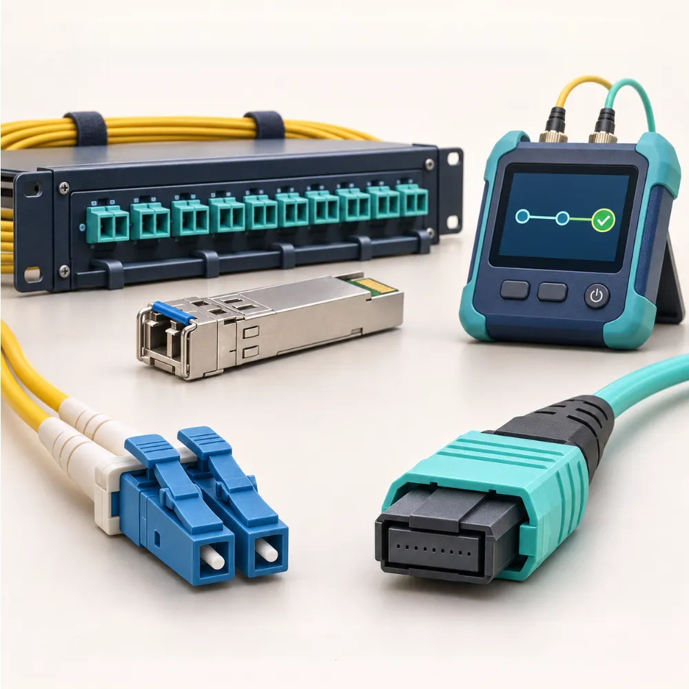
Compare exact optical modules
There is no single maximum distance for all MMF or SMF links. Speed, optical standard, fiber grade, and channel conditions change the result. These Cisco specifications show why single mode vs multimode fiber distance needs an exact part number.
| Cisco model | Rate and application | Specified fiber | Published maximum reach | Optical connector |
|---|---|---|---|---|
SFP-10G-SR | 10GBASE-SR | OM3 / OM4 MMF | 300 m / 400 m | Dual LC/PC |
SFP-10G-LR | 10GBASE-LR | G.652 SMF | 10 km | Dual LC/PC |
QSFP-100G-SR4-S | 100GBASE-SR4 | OM3 / OM4 MMF | 70 m / 100 m | MPO |
QSFP-100G-LR4-S | 100GBASE-LR4 | G.652 SMF pair | 10 km | Duplex LC |
Sources: Cisco 10G data sheet and Cisco 100G data sheet, checked November 19, 2026. These are third-party specifications, subject to their cabling conditions and host support.
An OS2 route is a candidate for the SMF examples only after its fiber specification and loss meet the stated requirements. The table describes neither tested CREA DAS TECH installations nor current model availability.
Recheck the whole channel during an upgrade
Hypothetical example: Morgan plans to move a 90 m OM3 link from 10G to 100G. The distance fits the listed 10G SR limit, but exceeds the selected 100G SR4 model’s 70 m limit. Morgan removes that model from the purchase list and asks for a supported alternative or a cable change. Reusing the same route remains a design question, even though the old service worked.
That is the practical value of single mode vs multimode fiber analysis during an upgrade. OM4 gives the listed SR4 model a 100 m limit, but changing to OM4 still requires the right strands and interface. An OS2 alternative needs suitable SMF optics at both ends.
Compare the cost of a complete link
Price optics, installed cable, labor, testing, and spares
Single mode vs multimode fiber cost cannot be settled by comparing two patch-cord prices. Short-reach MMF optics can be economical, while some SMF options are competitive at short distances too. Obtain current prices for the exact supported parts.
For an existing OM3 or OM4 installation, include the cost of disruption before selecting OS2. For a new OS2 route, include its longer-term uses without assuming every future speed will work. An upgrade still depends on the chosen application.
| Cost item | Question for the quote |
|---|---|
| Optics at both ends | Are both exact models, quantities, and support requirements included? |
| Cable and passive parts | Are patch cords, panels, adapters, and all required strands included? |
| Installation | Does the scope include routing, termination, access, and change windows? |
| Acceptance tests | Which fiber-matched tests and reports will be delivered? |
| Operations and spares | Which replacement parts and maintenance tasks will be needed? |
Hypothetical example: Alex has a documented 40 m OM4 channel and needs 10G today. Their installer finds that reuse is a valid candidate, subject to loss tests and supported optics. Alex asks for two complete quotes: reuse the channel or install OS2.
The decision then includes labor and testing, rather than assuming the lower cable price wins. No saving is known until those quotes arrive.
For single mode vs multimode fiber budgeting, keep today’s required service separate from possible upgrades. Record the expected lifetime, spare strategy, and likely next speed beside each option. This exposes assumptions that a unit-price table can hide.
Building the order list? Use the Cisco networking equipment procurement guide to organize exact part numbers and purchasing checks. Confirm condition, warranty terms, and delivery details for the specific quotation.
Match optics, connectors, and the installed cable
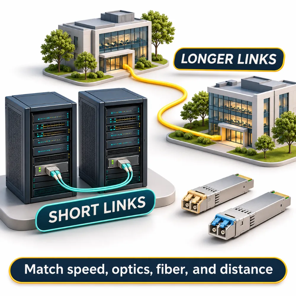
Separate the fiber type from the connector
LC is a connector format, not a fiber mode. Both SMF and MMF links can use LC. In a single mode vs multimode fiber check, matching the plug shape is only one step.
The listed 100G SR4 module uses an MPO interface and parallel fibers; Cisco describes a 12-fiber cable assembly. That does not mean all 12 positions carry active optical lanes. Its strand layout differs from the duplex pair used by the listed LR4 module.
Check connector polish too. Cisco’s cited 10G family note permits PC or UPC patch cords and excludes APC. PC means physical contact, UPC means ultra physical contact, and APC means angled physical contact; apply the exact module’s instructions.
For OM3 and OM4 channels, record strand count and polarity, which maps each transmitter to the correct receiver. For an OS2 channel, record those details as well. Neither cable category fixes a reversed connection or an unsupported optic.
Check loss, receiver limits, and test records
Single mode vs multimode fiber planning also needs an optical loss budget. Add the expected fiber, connector, and splice losses, then check the exact application’s permitted channel loss and optical power limits. Allow the design margin required by the application and project.
The FOA loss-budget guide explains how these losses accumulate. Too little received power can prevent a link; excessive received power can overload a receiver. Do not select an attenuator without checking the model’s limits and measured conditions.
An optical loss test set (OLTS) measures insertion loss. An optical time-domain reflectometer (OTDR) helps locate and characterize events along the route. Use fiber-matched test equipment and launch conditions; an OTDR trace alone should not replace the required acceptance measurements.
Use a six-step fiber selection worksheet
Turn single mode vs multimode fiber into a documented design decision. Give each proposed connection its own worksheet, with both endpoints listed. An existing OM3 or OM4 run and a proposed OS2 run should each have their own evidence.
- Record the service and endpoints. Note the required rate, both host models, ports, and software versions. Identify any breakout requirements.
- Measure the routed channel. Include patch leads and cross-connects. Record the actual path length rather than the distance between rooms.
- Identify the complete cable. Record OM3, OM4, OS2, or the actual alternative, plus fiber specifications and every intervening component. Flag missing records.
- Match the optical application. List both exact optics, wavelengths, connectors, polish, strand count, and polarity. Confirm peer interoperability.
- Check support and test limits. Verify host support, permitted reach, channel loss, and receiver limits. Attach the applicable test reports.
- Compare complete proposals. Include installation, passive parts, tests, spares, and order terms. Record who must resolve each open item before purchase.
For single mode vs multimode fiber approval, a blank field is an action item. If an OM3 test report is missing, obtain it. If an OM4 route exceeds the chosen optic’s limit, revise the design instead of treating a working older link as proof.
Hypothetical example: Taylor plans a 600 m inter-building route. The listed short-reach MMF examples do not cover it, so Taylor investigates a suitable SMF design. They ask the installer to specify the OS2 cable construction, route conditions, and loss tests, while checking both endpoints for supported optics. The outcome is a defined design request, rather than an unverified order for “long-distance fiber.”
The same worksheet makes a single mode vs multimode fiber discussion useful to purchasing staff. It links the cable label to the application, evidence, and parts that the quote must actually cover.
Fiber selection questions and next steps
Is single mode always better?
No. Single mode vs multimode fiber depends on the application. Existing OM3 or OM4 may suit a supported short link; SMF may fit longer routes or a chosen upgrade strategy. Compare complete supported systems.
Can I mix single-mode and multimode fiber directly?
Do not treat them as interchangeable sections of one passive channel. A mismatch can cause substantial loss. Changing the cable mode needs a supported design and suitable optics, not merely an adapter with the same connector shape.
Do LC connectors identify the fiber mode?
No. LC connectors appear on both types. Read the cable grade and module specifications; an LC plug alone cannot settle single mode vs multimode fiber compatibility.
Does OM4 increase speed by itself?
No. OM4 can support different reach limits from OM3 for a particular application, but it does not change the port rate. OS2 likewise needs the right optics and supported endpoints to deliver the intended service.
Is single-mode fiber always more expensive?
No. Single mode vs multimode fiber pricing changes with the optics, passive parts, installation, and existing plant. Compare current whole-link quotations instead of using a fixed price ratio.
Your next step
Start your single mode vs multimode fiber decision with the route you must serve. Identify the existing grade, confirm the required speed, and choose an optical application that fits both endpoints. Keep the exact model’s reach and loss limits beside the proposed cable details.
OM3 and OM4 can remain useful when the chosen application supports the full channel. OS2 can support a suitable SMF design, but its label alone is not an acceptance test. Connectors, polarity, and the loss report still belong in the approval record.
Before ordering, compare a complete bill of materials rather than one module or cable. Include installation work, passive parts, testing, and spares so each proposal covers the same service.
For a sourcing enquiry, send CREA DAS TECH your link requirements: endpoint models, software, target rate, routed length, cable grade, and available test reports. State any unresolved fields with the request. Those details give your single mode vs multimode fiber discussion a concrete starting point for checking candidate parts and quotation terms.