An optical transceiver converts electrical data into light for transmission over fiber and converts received light back into electrical data. Choose it by matching both host ports, the optical interface, and the installed fiber; a module that fits can still leave your link down.
You might have the right connector, a familiar brand, and enough advertised reach, yet still face a compatibility problem. One end could require a different port mode, or the patch panel could carry a different fiber type. Ordering another module before checking those details repeats the same uncertainty.
This guide gives you a practical sequence for selecting an optical transceiver, from SFP-family modules to QSFP28 and higher-speed links. It explains which labels help, which need a data sheet, and what to record before requesting a quote. The specification examples come from named Cisco models, with sources beside the relevant decisions.
You’ll also get a worksheet for both ends of a link. Use it to connect the engineering requirements to the purchase order, so substitutions and compatibility checks remain clear when the equipment arrives.
Key Takeaways
- Match the host, port mode, optical standard, and fiber at both ends; physical fit alone doesn’t establish compatibility.
- Cisco’s documented 10G SR and 100G SR4 examples have different reaches on the same OM3 fiber: 300 m and 70 m, respectively.
- A QSFP28 label identifies a module family; it doesn’t establish connector type, reach, FEC settings, or breakout support.
- Record exact part numbers, software, fiber details, and substitute approval before ordering an optical transceiver.
What an optical transceiver does
Follow the signal in both directions
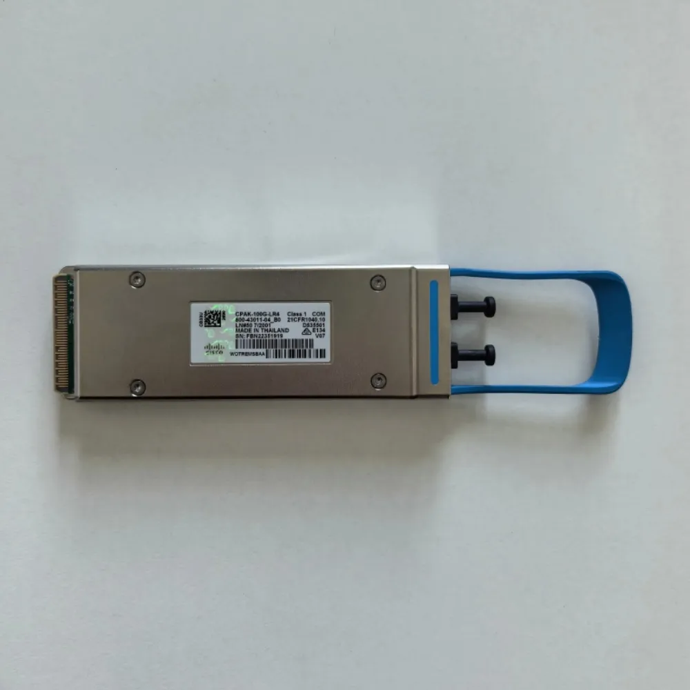
Inside an optical transceiver, the transmit side turns the host’s electrical signal into an optical signal. The receive side detects incoming light and returns an electrical signal to the host. This is the function described in Juniper’s optical-transceiver overview, now hosted in HPE’s documentation.
The module works as part of a link. The peer’s optical interface must work with it. The fiber must also meet that interface’s limits. An optical transceiver can’t bridge two network protocols just because their plugs look alike.
Ethernet and InfiniBand are different network protocols. Each link needs host and module support for the protocol in use. Check this before reach or price. The compatibility check starts with the gear at each end.
Browse the Cisco optical module catalog to find relevant product families. Then check the exact part against the host’s support list. A listing helps you start the search; confirm stock and order terms for the proposed purchase.
Distinguish optical modules from copper plugs
Small Form-factor Pluggable (SFP) names a module family. That name alone doesn’t mean it uses fiber. An RJ45 copper SFP sends electrical signals over twisted-pair cable. It isn’t an optical transceiver, though it fits an SFP-shaped host port.
An SFP optical module connects the host to fiber. Watch for purchase lists that say only “transceiver.” Record the medium, optical standard, and form factor together. Those details tell the supplier which type of part you need.
Duplex optics commonly use separate paths to send and receive light. Bidirectional, or BiDi, designs can use one fiber. The two ends use paired wavelengths, with each end receiving what the other sends. Count the fiber paths before choosing a module.
Compare optical transceiver types and host ports
SFP and QSFP families describe packaging
Form-factor names narrow the search, but they don’t finish it. An optical transceiver has a host side and a fiber side. Each side has its own needs. A QSFP28 label alone won’t tell you which fiber plug to use.
Use the table to find the right documents. These are common Ethernet uses. Exact support and speed limits still depend on the host and module.
| Family | Common Ethernet association | What still needs checking |
|---|---|---|
| SFP | 1G optical links | Exact SFP model, port speed, optical standard, and fiber |
| SFP+ | 10G optical links | Host support for the selected module and operating speed |
| SFP28 | 25G optical links | Port mode, optical interface, and supported FEC |
| QSFP+ | 40G optical links | Optical lane arrangement and supported host configuration |
| QSFP28 | 100G optical links | QSFP28 part number, connector, optical standard, and reach |
| QSFP-DD / OSFP | 400G and higher-speed implementations | Exact cage, host interface, operating mode, power, and cooling |
QSFP means Quad Small Form-factor Pluggable; DD means Double Density. OSFP means Octal Small Form-factor Pluggable. Their host connections differ. The host must support the chosen module and speed.
A QSFP28 optical transceiver can use parallel fibers. Another design can send several wavelengths over a fiber pair. The cases can look alike while the cables differ. Read the full optical interface name before reusing a patch cable.
Confirm the port’s supported operating mode
Start with the exact switch or adapter, line card, port, and software release. Find the supported optical transceiver part number and its setup notes. A chassis family name can be too broad for a compatibility check.
A port that accepts one SFP-family module may not accept all speeds in that family. Don’t assume a QSFP-DD host accepts every QSFP28 module either. Check the host’s listed modes, hardware, and software.
Check support in the right direction: can this host run this module? A faster optical transceiver won’t upgrade a slower host port. A new fiber plug won’t turn a QSFP28 module into a different form factor either.
Save the document version or lookup date with the proposed part. If software changes before the work starts, repeat the compatibility check. Give the site team exact settings to verify. A claim that the optic “works with this brand” leaves those details open.
Match fiber, reach, and connectors
Read the full optical standard
Single-mode and multimode fiber carry light in different ways. Check the installed fiber grade and path length from records or tests. Don’t specify an optical transceiver from jacket color and a plug photo alone.
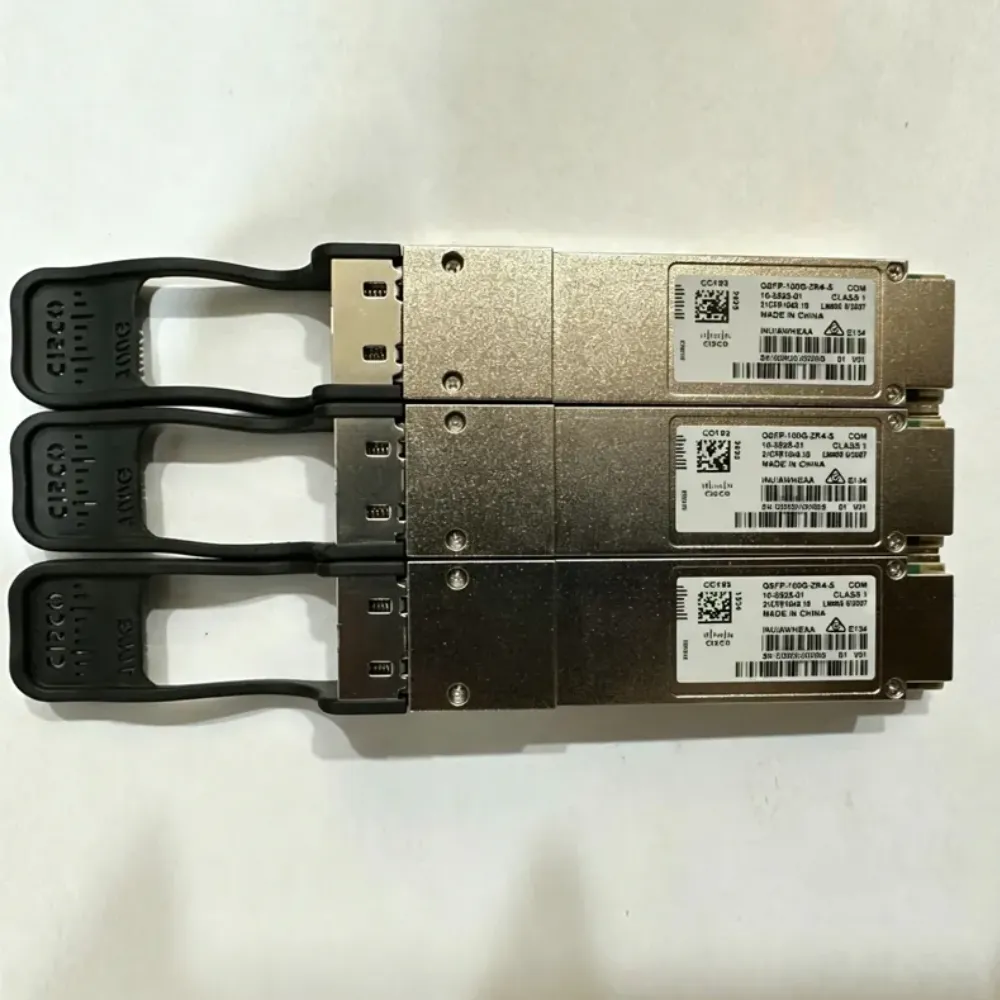
Read SR or LR with the data rate and full interface name. A reach quoted for one optical transceiver doesn’t apply to all modules marked SR. These Cisco examples show why.
| Exact Cisco model | Optical interface and medium | Documented reach | Connection |
|---|---|---|---|
SFP-10G-SR | 10GBASE-SR, 850 nm multimode | Up to 300 m on OM3; 400 m on OM4 | Dual LC/PC |
SFP-10G-LR | 10GBASE-LR, 1310 nm G.652 single-mode | Up to 10 km | Dual LC/PC |
QSFP-100G-SR4-S | 100GBASE-SR4, 850 nm multimode | Up to 70 m on OM3; 100 m on OM4 | MPO parallel-fiber connection |
QSFP-100G-LR4-S | 100GBASE-LR4, G.652 single-mode pair | Up to 10 km | Duplex LC |
The 10G SFP+ SR example and the 100G QSFP28 SR4 example both use 850 nm multimode transmission. Their reaches and fiber arrangements still differ. Matching wavelength therefore cannot establish optical compatibility by itself.
Hypothetical example: Alex plans a 100G upgrade across an existing 90 m OM3 route. The old 10G SR link fits its stated 300 m reach. The first proposed order therefore keeps the same fiber. But the QSFP28 SR4 data sheet gives a 70 m OM3 limit and a different fiber connection.
Alex holds the order and asks the team to review the optical transceiver and fiber path together. The design request goes back for revision before buying. This example shows an order decision; it isn’t a report of a tested customer deployment.
Check polarity and complementary wavelengths
On a duplex link, light sent from one end must reach the other end’s receiver. Check the full route through patch panels and trunks. With parallel optics, check the MPO cable, polarity, and lane map for that exact interface.
Connector polish also matters. Cisco’s cited 10G SFP+ document supports PC or UPC patch cords for the listed modules and excludes APC patch cords. Apply that note to the documented products; don’t turn it into a rule covering every optical transceiver.
For BiDi optics, record the wavelengths sent and received at each end. Match the send side to the peer’s receive side. Two parts with the same label aren’t proof of a working pair. Check host compatibility for each one as well.
Finally, inspect and clean fiber connections using the site’s approved procedure before testing. Follow the equipment’s laser-safety instructions and never look into a live optical port. A correct optical transceiver selection still needs a sound physical path.
Verify compatibility for 100G and 400G links
Separate host support from optical interoperability
Treat compatibility as three checks. Can the local host run its optical transceiver? Can the remote host run its module? Can the two optical interfaces work across the planned fiber path?
One answer doesn’t settle all three. A host can recognize a QSFP28 module even when the peer’s optical interface won’t work with it. Two optics that work together can also lack support in one host. Keep both checks on the record.
Use the vendor’s device-to-optics table for local support. Where available, use its optics-to-optics table to check the pair. Cisco’s compatibility-matrix user manual explains the device and module lookup approach.
Record exact product IDs and software conditions. A brand-wide claim leaves too much open.
Supplier coding is a separate issue. A module coded for a host may still lack that vendor’s support. Coding also doesn’t prove the pair will work or set the warranty terms. Ask what the compatibility claim covers and keep the supporting records.
For multi-vendor sourcing, CREA DAS TECH’s catalog includes Mellanox optical modules. Evaluate each proposed optical transceiver against its intended Ethernet or InfiniBand host and protocol; the category name doesn’t prove a particular configuration is supported.
Record FEC, breakout, and power requirements
Forward error correction (FEC) helps a link recover from some errors in the data stream. The required mode depends on the optical interface and host. Don’t turn FEC on or off for every QSFP28 link by a blanket rule.
Cisco’s 100G data sheet lists QSFP-100G-LR4-S as a 100GBASE-LR4 module. That standard doesn’t employ FEC. Other optical interfaces have different needs. Cisco’s optics implementation guidance provides the context; verify the exact host configuration at both ends.
Breakout splits a suitable high-speed port into lower-speed links. It needs a supported port mode, the right optical transceiver or cable, and the correct lane map. Four lanes inside a QSFP28 design don’t prove that any four slower peers will work.
Cisco’s breakout guidance directs readers to platform and software support information. Apply the same discipline when a 400G design connects to lower-speed equipment. Specify each resulting link rather than writing only “breakout cable” on the order.
Check power and cooling too. An optical transceiver must fit the port’s power limits and the system’s operating conditions. Check these for QSFP28 options and for QSFP-DD or OSFP gear. Reach alone can’t decide the choice.
Choose the medium and check the optical link
Compare DAC, AOC, and separate modules
A direct attach copper (DAC) cable links host ports over copper. Passive and active designs have different needs. Don’t assume they all use the same power. Check support for the exact cable and length at both ends.
An active optical cable (AOC) combines fiber and optical conversion in one cable assembly. Separate modules plug into a fiber path you can detach. Think about how you will route and replace each option. Check whether the choice can use the fiber already in place.
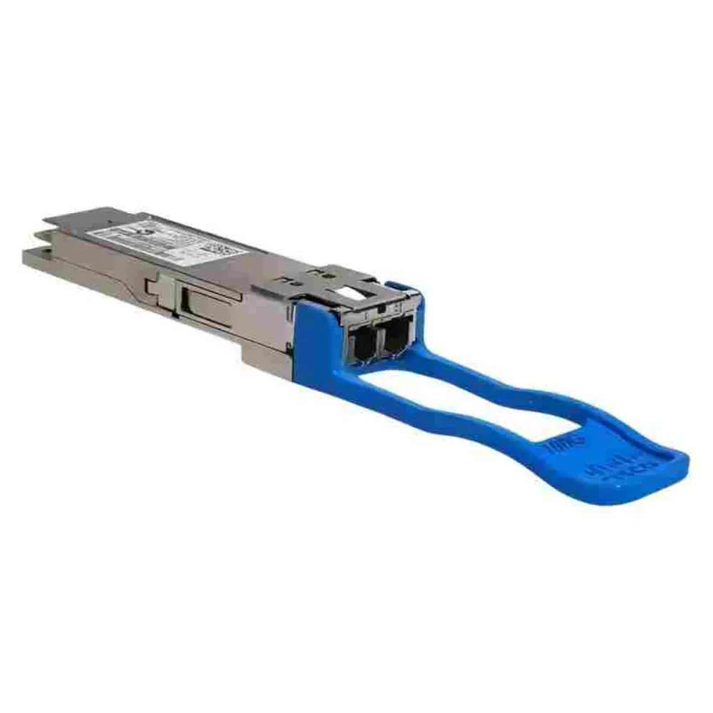
For a short QSFP28 connection between nearby racks, compare supported DAC and AOC options with separate modules. An optical transceiver pair may be more suitable when the route uses structured fiber or needs separately replaceable components. The decision depends on the actual installation and quoted parts.
Compare the total link cost: both endpoints, patch cords, adapters, installation work, spares, and support terms. There’s no universal price winner for every speed and route. SFP-family and QSFP28 assemblies also need their own compatibility checks even when the cable is supplied as one piece.
Budget loss and watch for receiver overload
Distance is only one part of the optical path. Plugs, splices, patch panels, and fiber all add loss. An optical transceiver link must stay within its optical limits. Leave the design margin required for that link as well.
Use the transmitter and receiver specifications for the exact interface, keeping the power measurement basis consistent. Optical power is expressed in dBm; loss and margin are expressed in dB. Don’t mix average-power and optical-modulation-amplitude limits without the manufacturer’s prescribed method.
Consider a hypothetical loss budget of 8 dB. The planned path uses 5 dB, and the reserve is 1 dB. The remaining headroom is 2 dB. These design inputs aren’t product limits for any SFP or QSFP28 model in the table.
Also check the receiver’s maximum input. A short path can deliver too much light even when the minimum receive level is met. Use an attenuator only when the design calls for one. Include its loss in the checks for both directions.
Interpret supported DOM readings
Digital optical monitoring (DOM), also called digital diagnostics, can report a module’s operating readings. The available readings depend on the optical transceiver and host. They can include sent and received optical power, temperature, laser bias current, and supply voltage.
Cisco’s DOM sensor specification lists those measurements for its documented products. Confirm which readings your host exposes and which warning thresholds apply. The absence of a reading alone doesn’t prove a failed module.
When diagnosing a link, check port state and module recognition first, then speed, FEC, peer interface, and fiber polarity. Compare optical readings with the applicable limits and inspect the path. DOM supports fault isolation; it doesn’t replace link acceptance testing or establish compatibility for an unlisted part.
Build a two-end optics request
Copy the requirements worksheet
A request for quotation (RFQ) should describe the whole link. An optical transceiver order that says only “100G QSFP28, 10 km” leaves open questions. The host, optical interface, software, plug, and support terms can still differ.
Copy this worksheet into the bill of materials (BOM). Fill it in for each link type and name the owner of each open field. Is the far end outside your control? Get its equipment details before you approve the pair.
| Field | Endpoint A | Endpoint B / shared route |
|---|---|---|
| Link identifier and owner | Record site, rack, and link ID | Name the remote owner |
| Host and line card | Exact model and hardware revision | Exact model and hardware revision |
| Port and software | Port identifier and release | Port identifier and release |
| Required operation | Protocol, speed, and port mode | Matching peer operation |
| Optical transceiver | Exact proposed product ID | Exact peer product ID |
| Optical interface | Full standard or documented interface | Interoperable peer interface |
| Wavelengths, if relevant | Transmit and receive values | Complementary values for BiDi |
| Fiber and length | Grade and installed route | End-to-end length and records |
| Connector and polarity | Interface and polish | Patch-panel path and mapping |
| Optical limits | Applicable transmit/receive limits | Path loss, overload, and margin check |
| FEC and breakout | Required mode and child-port mapping | Peer settings and connections |
| Power and environment | Port budget and operating conditions | Remote budget and conditions |
| Quantity and condition | Installed units and agreed spares | Agreed hardware condition |
| Compatibility evidence | Source, revision, and lookup date | Peer evidence and configuration |
| Substitution approval | Exact approved alternative, if any | Named approver and approval date |
| Receiving evidence | Identity, condition, and agreed checks | Test record and acceptance owner |
Keep technical requirements separate from commercial terms. Ask the quotation to state availability, delivery arrangements, warranty coverage, returns, and any support scope. An optical transceiver specification or compatibility result doesn’t establish those terms.
For wider purchasing context, use our Cisco procurement guide alongside this worksheet. It helps connect individual parts to the broader equipment purchase.
Approve substitutions before ordering
Check a replacement optical transceiver against the whole worksheet. Speed and reach alone aren’t enough. A QSFP28 substitute can change the optical interface, plug, FEC mode, or operating limits. Its host-support status may differ too.
Hypothetical example: Jordan is collecting quotes for 12 QSFP28 links. SFP+ management uplinks sit on separate order lines. One offer replaces the requested duplex-LC optics with parallel-fiber modules at the same speed. Jordan checks the worksheet: the installed route has duplex single-mode pairs.
The offer goes back for revision before approval. Separate QSFP28 and SFP+ lines also keep the compatibility questions clear. Neither the quote nor this example proves that a supplier has tested the link.
Ask for sourcing and condition records when those are part of the purchase requirements. Proof of origin, compatibility records, and test results answer different questions. Keep each for its own purpose. Agree on receiving checks before accepting delivery.
Optical transceiver questions and next steps
Can the two ends use different brands?
Yes, if each host supports its local optical transceiver and the two optical interfaces work together over the chosen path. Brand matching alone doesn’t settle compatibility. Record both interfaces and the host conditions. Check support terms as a separate part of the purchase.
Can separate ports use single-mode and multimode fiber?
Yes, if each port and module support the intended link. Separate ports can serve different fiber paths. That doesn’t make the paths interchangeable. Check each optical transceiver with its own peer, fiber grade, plug, and reach.
Will a 1G SFP work in a 10G SFP+ port?
Only if the host documents support for that SFP module and operating mode. Similar dimensions aren’t enough. Check the exact port, software, and part number before reusing a 1G SFP; apply the same host-specific approach to QSFP28 and higher-speed cages.
Can I pair SR and LR optics on one link?
Don’t treat SR and LR as an interchangeable pair. Their optical specifications and intended fiber paths differ. Check the complete interface at each end; matching the connector or nominal Ethernet rate doesn’t establish compatibility between them.
Why does a module fit but fail to link?
Possible causes include unsupported host operation, a mismatched peer interface, incorrect speed or FEC, fiber polarity, contamination, or excessive path loss. Check recognition and configuration before replacing the SFP or QSFP28 module. Change one variable at a time and retain the test results.
Your next step
Start with the two endpoints, then check the optical interface and fiber path. The form factor narrows the choices. The exact module and host documents show whether a pair fits your design. Read reach with its stated fiber and operating conditions.
Before you order, complete the worksheet for one representative link and resolve its open fields. Check the host models, software, module part numbers, connectors, and optical limits together. Record FEC and breakout settings where they apply, and keep the compatibility evidence with the approved bill of materials.
For existing infrastructure, distinguish what you know from what still needs testing. A working older SFP link doesn’t prove that a new QSFP28 design can reuse its fiber unchanged. Likewise, a successful bench link doesn’t establish warranty terms, long-term support, or acceptance of an unapproved substitute.
When you’re ready to select an optical transceiver, request a quote from CREA DAS TECH with both endpoints, the fiber route, quantities, and required condition. Ask for the proposed parts and commercial terms in writing so you can review the complete link before approving the order.