Key Takeaways
- Match the module’s data rate, wavelength, fiber type, and connector to the network equipment and cabling.
- Check the supported transmission distance against the actual fiber route and channel loss.
- Confirm host-device compatibility, firmware support, and required FEC settings before purchasing.
- Compare transmit power, receiver sensitivity, and maximum receive power to assess the optical link budget.
- Request test records, compatibility confirmation, and written warranty terms from the supplier.
Introduction
As data center traffic grows, 25G connections provide a practical way to increase bandwidth between servers, switches, and other network devices. However, choosing an optical module involves more than matching a speed rating. Fiber type, transmission distance, host compatibility, and error correction settings all affect whether a link can operate reliably.
For network administrators and B2B buyers, the selection process should start with the existing network architecture. This guide explains the technical specifications to compare, the compatibility checks to complete, and the purchasing details to confirm before placing an order.
What Should You Know Before Choosing a 25G Optical Module?
Understanding the module’s role and interface is the first step. These basics help narrow down suitable options before you compare detailed specifications.
What Is an Optical Module and How Does It Work?
A Fiber optic module converts electrical signals from a switch or server into optical signals for transmission through fiber. At the receiving end, another module converts the incoming optical signals back into electrical signals.
A typical optical link uses two transceivers connected by a fiber pair. One transceiver sends data through its transmitter, while the other receives it through its optical receiver. Both ends must use compatible wavelengths, fiber types, and transmission standards.
The module must also match the host device’s port and supported data rate. A physical fit alone does not guarantee that the link will operate correctly.
How Do SFP+, SFP28, and QSFP28 Interfaces Differ?
The form factor indicates the module’s physical interface and the type of port it is designed to use.
- SFP+: Commonly used for 10G connections.
- SFP28: Designed for 25G connections and similar in physical size to SFP+.
- QSFP28: Commonly used for 100G connections, often through four 25G lanes.
Although SFP+ and SFP28 modules share a similar form factor, they are not automatically interchangeable in every device. Port capabilities depend on the host hardware, firmware, and manufacturer configuration. Check the equipment documentation before assuming that a port supports both speeds.
When Is 25GBASE-SR Suitable?
25GBASE-SR is a short-reach optical standard designed for multimode fiber. It is commonly considered for connections within data centers, server rooms, and enterprise network facilities.
This type of link is suitable when the fiber route is relatively short and the installed cabling supports the required transmission performance. It is not the default choice for every 25G connection. Longer routes may require a single-mode solution, while very short connections within a rack may be more economical with direct-attach copper cables.
Which Technical Specifications Should You Compare Before Buying?
Once the interface and application are clear, compare the optical specifications against the actual cable route and host requirements. A mismatch in any of these areas can cause link instability or prevent the connection from coming up.
How Should You Match Data Rate, Wavelength, and Connector Type?
Start with the port speed. Both ends of the link must support the intended data rate, and the host port must be configured accordingly. When comparing SFP28 module specifications, check that the module is designed for the required 25G application rather than relying on connector shape alone.
Next, match the wavelength and fiber type. Short-reach multimode modules commonly operate around 850 nm, while many long-reach single-mode modules use wavelengths around 1310 nm. These options are designed for different fiber infrastructures and should not be mixed without explicit support.
Connector type also matters. Many multimode modules use duplex LC connectors, but buyers should confirm the connector and fiber polarity of the installed cabling. Check the required end-face type as well. An incompatible patch cord can affect optical performance.
How Do OM3, OM4, and OM5 Affect Transmission Distance?
OM3, OM4, and OM5 are multimode fiber grades with different bandwidth characteristics. The supported distance depends on the transceiver specification, fiber grade, and the quality of the complete optical channel.
Do not estimate reach from the fiber label alone. Check the module’s published distance for the exact fiber grade. Also account for patch panels, connectors, splices, and cable condition. These components contribute to channel loss and may reduce the available link margin.
For an existing network, confirm the cable type and route length before ordering. If the distance is close to the module’s rated limit, ask the supplier or network team to review the channel loss budget.
How Do Optical Power and Receiver Sensitivity Affect Link Performance?
Transmit power indicates the optical signal level leaving the module. Receiver sensitivity describes the minimum signal level the receiving module can detect within its specified operating conditions. The difference between the available transmit level and receiver sensitivity helps determine whether the link has sufficient optical margin.
Buyers should compare the transmitter’s minimum output power with the receiver’s sensitivity at the opposite end. They should also check the maximum permitted receive power. A signal that is too weak may cause errors or link loss, while an excessively strong signal can overload the receiver.
The link budget must account for losses from fiber length, connectors, patch panels, and splices. If the calculated margin is too small, the connection may become unstable as components age or connector conditions change.
What Can DOM/DDM Tell You About a Fiber Link?
DOM/DDM provides access to operating information such as transmit power, receive power, temperature, supply voltage, and laser bias current when these functions are implemented. The SNIA SFF-8472 specification defines a management interface for monitoring and controlling SFP+ optical transceivers and similar devices.
Monitoring data helps technicians identify changes in operating conditions. For example, a drop in receive power may indicate a dirty connector, damaged cable, or another issue along the optical path. However, DOM/DDM readings do not identify the exact cause. Physical inspection and optical testing may still be necessary.
Why Must You Check FEC Settings on a 25G Link?
Forward Error Correction (FEC) helps a receiver detect and correct certain transmission errors. The required mode depends on the transceiver, host platform, and link configuration.
Some 25G optical links require RS-FEC on the host port. If the switch and transceiver use incompatible settings, the link may fail to establish or may experience errors. Confirm the required FEC mode in the equipment and transceiver documentation, then verify that both ends use compatible settings.
How Can You Verify Compatibility and Choose a Reliable Supplier?
Before ordering, identify the exact host equipment and establish what evidence the supplier can provide. This reduces the risk of receiving modules that meet the optical specifications but do not work with the intended platform.
How Do You Check Switch and Server Compatibility?
Identify the exact switch or server model, port type, operating system or network platform, and firmware version. Then check the manufacturer’s compatibility documentation or request written confirmation from the supplier.
For third-party transceivers, check whether the host device accepts the module’s coding and whether its firmware recognizes the transceiver. Also confirm that the port supports the required speed and FEC configuration. For mixed-vendor networks, check both ends of the link and make sure the selected modules use matching optical specifications.
Which Testing Records Should You Request?
Ask the supplier what tests are performed on the delivered modules. Useful records may include:
- Transmit and receive optical power measurements.
- Wavelength and data-rate verification.
- DOM/DDM function checks, where supported.
- Compatibility or interoperability test results for the requested host platform.
- Product identification and serial-number records.
For larger orders, clarify whether test reports are available by batch or by individual unit. These records make incoming inspection easier and provide useful information if a link problem occurs after installation.
How Should You Compare Prices and Warranty Terms?
Do not compare an Optical transceiver only by its unit price. Consider whether the quotation includes the required coding, testing, packaging, and technical support. A lower initial price may not represent better value if compatibility checks or replacement procedures are unclear.
Ask the supplier to state the warranty period, coverage, replacement process, and any conditions that may affect a claim. For volume purchases, confirm whether the same specification and compatibility requirements apply to every unit in the batch. Keep the quotation, test records, and warranty terms together for future reference.
Why Choose CREA DAS TECH’s Cisco SFP-25G-SR-S Optical Module?
For buyers evaluating a Cisco compatible SFP for short-reach 25G connections over multimode fiber, the SFP-25G-SR-S is one option to consider. The following specifications are based on the product information provided for this model.
Key Product Specifications
| Parameter | Specification |
| Model | SFP-25G-SR-S |
| Form factor / data rate | SFP28 / 25Gbps |
| Standard / wavelength | 25GBASE-SR / 850nm |
| Optical source / fiber | VCSEL / Multimode Fiber |
| Transmission distance | OM3: 70m; OM4/OM5: 100m |
| Connector / functions | Duplex LC / DOM-DDM / RS-FEC support |
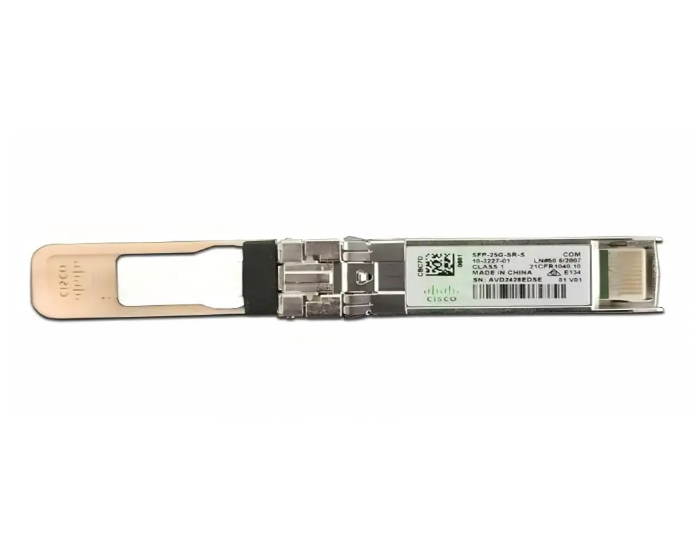
Short-Reach Connectivity for Data Center Deployments
This module is designed for short-reach 25G links over multimode fiber. It can be considered for server-to-switch connections and other links within data center environments where the installed fiber route falls within the supported distance.
For facilities with existing multimode cabling, a suitable short-reach transceiver can help expand 25G connectivity without requiring an immediate change to a single-mode fiber architecture. Buyers should still verify the installed fiber grade and total channel length before deployment.
850nm VCSEL Transmission for Multimode Fiber
The 850nm VCSEL optical source is designed for multimode fiber transmission. It is relevant to facilities that already use compatible multimode cabling for short-distance connections.
Before installation, check the fiber grade, connector condition, and polarity. A suitable transceiver cannot compensate for damaged connectors or an unsuitable cable route.
Duplex LC Connection for Structured Cabling
The duplex LC interface supports a two-fiber connection, with one fiber carrying transmit signals and the other carrying receive signals. This arrangement is commonly used in structured fiber cabling.
For replacement or expansion work, check the patch panel layout and polarity of the existing link. Confirm that the patch cords use the correct connector type and compatible end-face finish.
DOM/DDM Monitoring for Network Maintenance
DOM/DDM support can provide visibility into operating parameters such as optical power and module temperature, subject to the host platform and monitoring implementation.
Network technicians can use this information as part of routine maintenance and fault diagnosis. For example, a change in receive power may indicate a dirty connector, cable damage, or another issue along the optical path. Further inspection is still needed to identify the actual cause.
RS-FEC Support and B2B Purchasing Assurance
This model is specified with RS-FEC support. The host port must also be configured for the required FEC mode; buyers should verify this against the switch or server documentation before deployment.
For business orders, confirm the requested compatibility coding, test requirements, warranty coverage, and delivery terms in writing. The product offering lists a five-year standard replacement warranty. Confirm its applicable conditions and coverage for the actual order with the supplier.
Frequently Asked Questions About 25G Optical Modules
Is an SFP28 module the same as an SFP+ module?
No. They share a similar physical form factor, but SFP28 is designed for 25G operation, while SFP+ is commonly used for 10G. Whether a port supports both depends on the host device and its configuration.
Can this 25GBASE-SR module work with OM3 fiber over 80 meters?
No. The published distance for this model over OM3 fiber is 70 meters. An 80-meter route exceeds that stated limit. Consider an alternative designed for the required distance or review the cabling design before deployment.
Does the SFP-25G-SR-S require RS-FEC?
The manufacturer specifies RS-FEC on the host port for this transceiver. Confirm that the switch or server supports and enables the required mode.
Can a 25G SFP28 module be installed in any SFP+ port?
No. Similar physical dimensions do not guarantee operational compatibility. Check the host device’s supported transceiver list, port speed, and software configuration.
What is DOM/DDM used for?
DOM/DDM allows supported host equipment to read module operating information, including optical power and temperature. It helps with monitoring and troubleshooting but cannot replace optical power testing or physical inspection.
Conclusion
A 25G upgrade is easier to manage when transceiver selection is included in the wider network plan. Consistent module specifications across equipment groups can simplify deployment, reduce compatibility variables, and make future replacements easier to organize. Monitoring support can also give maintenance teams more information when investigating changes in link performance.
For growing data centers and high-performance computing environments, consider how today’s connections will fit into future server additions, rack layouts, and network capacity plans. Reusing suitable multimode fiber infrastructure can also reduce the need for immediate cabling changes when expanding short-reach connectivity. The key is to verify the fiber route, host platform, and optical link budget before deployment.
If you are evaluating optical modules for AI servers, GPU servers, or high-performance computing projects, contact CreadaTech with your server configuration, application requirements, and expansion plans. We can help review compatible options and provide a quotation based on your project needs.