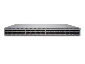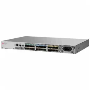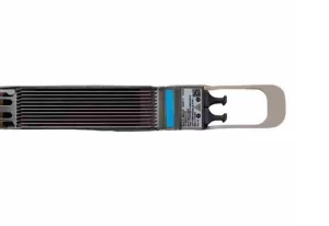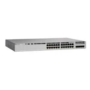
Cisco optics compatibility is the fit between a specific transceiver, a specific Cisco host, the port it plugs into, and the software running there. Cisco’s optics-to-device compatibility matrix is the place to confirm host support, but it answers only part of the question. A working link also needs matching optics at both ends, the right fiber, a supported port mode, and clear supplier terms.
You may know the failure mode. A module seats cleanly, the port lights, and then errors appear under load. Or a spare switch accepts the same optic as production but runs an older release. Both problems pass a quick visual check and fail a proper one.
This guide gives you a repeatable Cisco optics compatibility check, in the order that saves the most time. You will see how to read the matrix, how to match reach and wavelength, where port modes and diagnostics change the answer, and what to record before you request a price.
The official tool is only part of the job. The buyer’s record is what protects you when the hardware arrives on site.
Key Takeaways
- Verify compatibility for the exact device or line card product ID, port mode, and software release, not just the switch series.
- A physical fit and a supported host are different from an optical link that works across fiber and the far end.
- Copy the matrix row, optic product ID, software information, and source into the requirement before you order.
- Request order-specific details for condition, testing, warranty, and lead time when buying through a reseller.
Have the part numbers already? Browse Cisco optical modules to check the category, then send the exact PIDs for a quotation.
Start your Cisco optics compatibility check
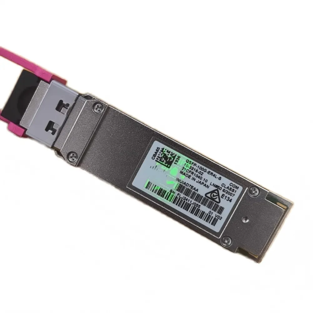
Cisco optics compatibility has four parts, and each fails for a different reason:
- Physical fit. Does the module match the slot and connector? An SFP cannot enter a QSFP28 cage, and an LC connector cannot mate with a different connector format.
- Host support. Does Cisco list the optic for that exact hardware and software? A switch family, or even a platform model, is not proof for every front-panel port.
- Optical link. Can both ends transmit and receive at the same speed, wavelength, and fiber mode within the allowed distance?
- Commercial and support terms. Does the quote show what the hardware is, how it was prepared, what testing it received, and the warranty for that order?
Start with the hardware’s product identifier. Then use the Cisco optics selector when you need a two-sided view. Cisco describes that tool as combining compatibility and interoperability for two network devices connected by Cisco optics and cables.
Write down sources, not memories. “A colleague confirmed it” is not a record you can hand to a network management team six months later.
Hypothetical example: A finance-sector infrastructure team, planning a branch refresh, ordered 10 SFP+ modules for a spare switch. The compatibility check passed on the 10G ports, but the spare had an older software image than production. The team’s change record caught the difference before deployment. Copying the software column would have caught it without a weekend call.
Use the Cisco optics compatibility matrix
The current Cisco tool lets you search by network device product family, network device product ID, transceiver product family, transceiver product ID, data rate, reach, cable type, or form factor. The tool user manual covers filters, hover notes, and Excel, PDF, or CSV exports. Its introduction says the tool determines which transceivers are supported in Cisco switches, routers, and line cards or modules.
That purpose matters. A Cisco compatibility matrix result answers a host-support question. It does not answer every question about a real fiber link.
Search by the right product ID
Start with the hardware’s actual product identifier rather than the family name. A Cisco Catalyst 9500 series has multiple models with different front panels. A line card adds another layer, because the module may plug into the card rather than the chassis.
For a switch and a transceiver, the most useful filter pair is the exact device PID plus the optic PID. If you have only a family name, narrow the query before you record the result.
The Cisco optics matrix exports results for a reason. A saved result lets procurement, engineering, and support cite the same row. Keep the device PID, optic PID, data rate, reach, cable type, form factor, and dashed notes together.
| Record field | What to write | Where to get it |
|---|---|---|
| Device PID and slot or port | Exact switch, router, adapter, line card, or module; port group if documented | Hardware label and platform documentation |
| Host software | Installed release; lowest release that will run the link | Current host inventory |
| Optic PID and standard | Exact module, data rate, wavelength, fiber mode | Matrix row and data sheet |
| Matrix evidence | Product IDs, result, access date, export file name | Current Cisco matrix |
| Link design | Distance, fiber grade, connector, polish, loss margin | Site survey and cable records |
| Support status | OEM or reseller-compatible; Cisco support status; supplier terms | Quote and supplier confirmation |
| Diagnostics | DOM needed? Supported on host and module? | Matrix notes and platform guide |
| Acceptance | Power readings and error counters before and after | Commissioning test |
Fill the gaps rather than guess. Mark unknown fields and make them a condition of the order.
Read the software column as part of support
The matrix reports software information, including minimum release support in the platform views Cisco describes. Cisco’s Catalyst 9000 fiber troubleshooting guide adds a warning that is easy to miss. The presence of an SFP in the matrix does not guarantee compatibility with a given interface, because standards can differ from port to port on one front panel.
The guide cites the C9500-32QC model as a case where standards vary. It tells readers to confirm against hardware installation notes.
Treat the row as support for a defined boundary. That boundary is the model, port or port group, installed release, and intended port mode. If production software differs from a lab switch, check both, or check the lowest release that will be in service.
Cisco’s manual is a reference document, not a live query. Labels and values can change. The current matrix row, with its access date, is the evidence to cite.
Know what the matrix does not prove
No Cisco transceiver compatibility tool can prove everything alone. It cannot prove fiber condition or installed loss, or that the far end supports the link. It cannot show whether a reseller’s module matches an OEM part. Nor can it prove that diagnostics work without the feature’s own requirements.
Record any gap. It tells the next engineer what remains to test.
Ready to confirm the quote against a matrix row? Send your drawlist, exact PIDs, software release, and link distance to the Cisco procurement guide review, or go straight to contact us with the requirements.
Match both ends of the optical link
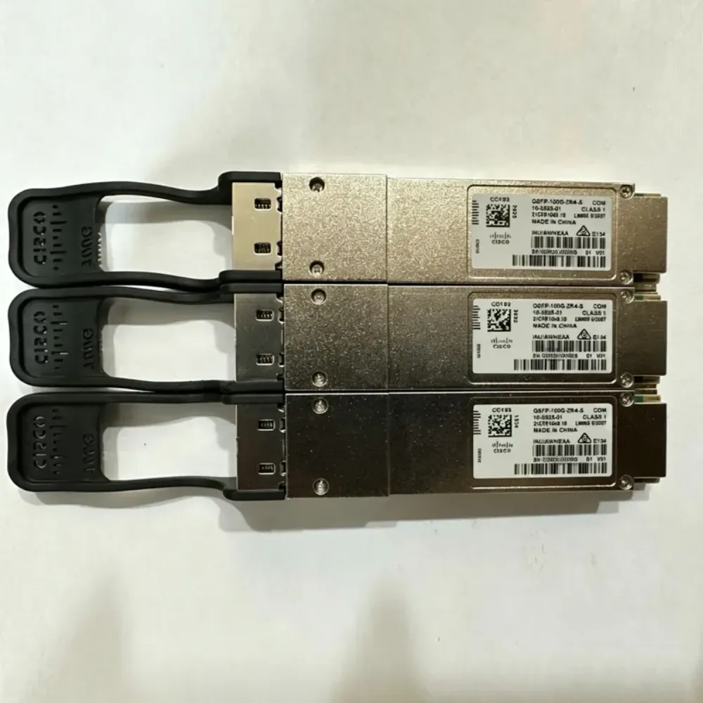
Host support gets the module recognized. The optical link gets the two ends talking. Cisco’s online tools blog separates the two. The Cisco optics matrix covers host support, while the interoperability matrix covers optical communication through fiber.
Cisco optics compatibility also depends on the far end. Two separately supported modules can still make a poor pair. Check speed, fiber type, wavelength, connector and polish, and distance at both ends.
Start with the form factor and speed
The SFP (Small Form-factor Pluggable) is a compact, hot-pluggable module that carries one link into a switch, router, or adapter. SFP+ is a 10 Gbps member of that family. QSFP28 and QSFP-DD are quad-lane families for higher per-port bandwidth. The form factor sets what can physically seat and what lanes the host expects.
A connector that fits does not guarantee every rate. The port’s supported speeds and the module’s rating must both be satisfied. A 1G SFP may be allowed in some SFP+ ports and rejected by other 10G-only ports. Cisco SFP compatibility is therefore a port-level question, not a brand-level one.
Compare SR and LR by fiber and reach
The exact Cisco 10GBASE SFP+ data sheet gives a concrete comparison for two common 10G modules. These figures describe Cisco’s modules and the stated fiber conditions. They do not describe every vendor’s part or every deployed link.
| Attribute | Cisco SFP-10G-SR | Cisco SFP-10G-LR |
|---|---|---|
| Ethernet standard | 10GBASE-SR | 10GBASE-LR |
| Nominal wavelength | 850 nm | 1310 nm |
| Fiber type | Multimode | Single-mode G.652 |
| Stated reach | 300 m on OM3; 400 m on OM4 | 10 km |
| Connector in data sheet cabling table | Dual LC/PC | Dual LC/PC |
The data sheet also states that SR reaches 26 m on older FDDI-grade multimode fiber, which shows why “SR” alone is not a distance. The fiber’s bandwidth grade sets the reach. OM3 and OM4 are laser-optimized grades whose distance limits shrink as link speed rises.
Neither module’s connector shape proves the link will work. The polish and fiber mode must match the intended interface. The far end must use a compatible standard.
Cisco’s fiber troubleshooting page notes that both SFPs must read and transmit on the same wavelength. Bidirectional modules separate transmit and receive wavelengths, so they must be paired conversely at the other end.
Budget the optical path, not the catalog number
Catalog reach is a maximum under specified conditions. Splices, patch panels, dirty connectors, and tight bends add loss. Use the data sheet’s optical budget and your measured or designed link loss, with margin for aging.
Hypothetical example: A data center team is designing a 250 m OM3 link and books SFP-10G-SR optics for both ends. The nominal 300 m reach fits on paper. The team still has to confirm exact host support at both ends, measure insertion loss through the patch panels, and check that both transceivers are SR and multimode. A 300 m rating without a loss budget is a plan, not a test.
For a 2 km inter-building run, the same logic points to single-mode fiber and an LR-class module. Two LR modules at 1310 nm do not make a multimode link work. Fiber mode and connector have to agree first.
Check port modes, FEC, and software support
A supported optic can still land in the wrong mode. Cisco’s Catalyst 9000 troubleshooting guide lists the dimensions that matter on those platforms: speed capabilities, connector and polish type, single-mode versus multimode, parallel or duplex cabling, wavelength, transmit and receive power, voltage and current, NRZ versus PAM4 signaling, FEC, and cable modal bandwidth.
The guide exists because a link can look fine at Layer 1 while errors build. Port mode is where a Cisco optics compatibility check often fails after the module has passed every other test.
Port mode decides what the optic can do
Some high-speed ports run as one wide link, while others split into breakout links. A 100G port might serve four 25G links with suitable optics and cabling. The matrix notes and hardware guide carry those rules.
Do not infer a breakout from the module’s label. The host has to support the mode, the optic has to be designed for it, the cable has to be correct, and the far-end ports have to match the split.
FEC follows the standard and the peer
Forward error correction adds redundant bits so a receiver can correct some bitstream errors. It matters for 25G, 100G, and 400G links. Cisco’s troubleshooting page says FEC is enabled by default on a Cisco host based on the detected optical module type. Implementation is usually dictated by the industry standard for that optic.
That is not a reason to force a setting on every link. Mismatched FEC expectations can stop a link from coming up or make it unstable. Check what the host reports, what the standard calls for, and what the far end expects.
Change configuration only with a planned, reversible change and a validated peer. The same discipline applies to NRZ and PAM4 signaling.
Diagnostics have their own support requirements
Digital optical monitoring, or DOM, reports live measurements such as transmit power, receive power, temperature, laser bias current, and supply voltage. Cisco’s data sheet says its 10G bidirectional modules support DOM according to the SFF-8472 multisource agreement.
Basic link support and diagnostics are not identical. Cisco’s troubleshooting guide says DOM is not integrated into all transceivers and that the minimum IOS XE version varies by host. A module can carry traffic without exposing the readings your monitoring team expects. If dashboards depend on optical readings, put DOM support in the requirement.
Diagnose a module that fits but will not link
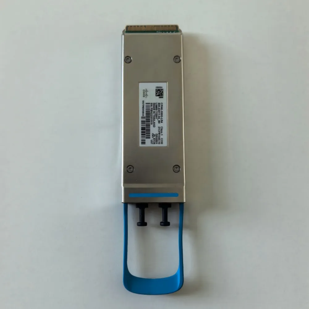
Start with evidence. Replacing the module first can hide a fiber or software problem, and the next part may repeat the fault.
Cisco’s Catalyst 9000 guide gives read-only examples for those platforms. Use the exact syntax for your release and platform. Do not assume IOS XE commands apply to NX-OS or IOS XR. The guide’s examples include show interfaces transceiver supported-list, show idprom interface, show interfaces with capabilities, and show interfaces with transceiver detail.
A practical order:
- Confirm the host sees the part. If the host has no module record, check seating and slot support before changing fiber.
- Confirm port mode and speed. Compare configured speed with the module and the far end.
- Read optical parameters. Cisco’s guide says low receive power most often points to the far-end transceiver, far-end device, or cable. High receive power is also a warning, and a faulty DOM sensor is possible.
- Check FEC and signaling. Compare both ends and the optic’s standard before changing configuration.
- Inspect the physical path. Connector type, polish, cleanliness, polarity, and bend radius all matter.
Separate coding questions from support questions
Many non-OEM modules are coded for Cisco hosts. Cisco’s position is explicit: it does not support third-party optics, and inserting non-compatible or third-party SFPs can cause unpredictable behavior. That is Cisco’s support boundary, not a verdict on every module on the market.
For a buyer, three ideas can diverge:
- Host recognition means the platform identifies the module enough to bring up an interface.
- Cisco support means the combination sits in Cisco’s supported envelope.
- Link performance means the optical pair, fiber, and settings actually work.
A module may link yet sit outside Cisco support. An OEM module may be supported yet fail its optical budget. Ask your supplier which of the three they are claiming, and put it in writing.
Hypothetical example: A telecom integration team, staging a temporary ring extension, used third-party coded modules to match an existing coded inventory. The link came up, so the team moved to commissioning. During a peak test, error counters rose, and the team had no optical baseline for comparison. Their next order will save pre-deployment readings and the exact support status, OEM or compatible.
Frequently asked questions
Do all Cisco SFP modules work in all Cisco switches?
No. SFP is a form factor, not a universal compatibility promise. The exact switch or line-card PID, the port or port group, the software release, and the port mode all affect support. Use the current matrix and the platform hardware notes for the combination in front of you.
Can I put a 1G SFP in a 10G SFP+ port?
Sometimes, depending on the platform and port. SFP+ ports often accept lower-speed SFPs, but not every port supports every rate. Check the product documentation for the exact model and confirm the configured speed. A connector that fits is not enough.
What is the difference between SR and LR optics?
SR is a short-reach multimode standard, commonly at 850 nm, and its distance depends on the fiber grade. LR is a long-reach single-mode standard, commonly at 1310 nm, with a 10 km rating in Cisco’s 10G data sheet. Choose by fiber type, distance, and the support listed for both hosts.
Are third-party Cisco-compatible optics supported by Cisco?
Cisco’s matrix states that Cisco does not support third-party optics, and its troubleshooting guide warns that non-compatible or third-party SFPs can behave unpredictably. A reseller may offer its own testing and warranty terms. Those are not the same as Cisco support, so ask for the distinction in writing.
Why does my module link but show no optical readings?
The module may lack digital optical monitoring, or the host may not expose it. Basic link support and DOM support have separate requirements. Check both in the matrix and platform documentation.
Document the result before ordering
A compatibility record protects the buyer, the engineer, and the supplier from a disagreement about what was ordered. Build it beside the bill of materials, and mark any unknown field as a condition of the order.
The record should let another team reproduce the check: exact product IDs, the software release, the matrix row and access date, the fiber type and distance, and the support terms. That turns “Cisco 10G optics” into a defined part with a defined support boundary.
A current record also speeds up warranty conversations, because the buyer can show which module was specified and which support terms applied.
Cisco optics compatibility comes down to evidence you can re-check: exact host and port, optic and standard, both fiber ends, software in service, and support terms. Do that once and keep it.
Have a Cisco optics compatibility question or a part list? Send your requirements to CREA DAS TECH for exact items, testing, warranty, and lead-time terms.