Key Takeaways
- Match the transceiver to the network architecture, port configuration, and required transmission distance before comparing prices.
- Check whether the installed fiber is single-mode or multimode. The fiber type must match the optical interface.
- Confirm fiber grade, connector type, polarity, and link loss before ordering.
- Verify the host device’s port support, module form factor, cooling design, and protocol compatibility.
- Evaluate the complete link, including transceivers, fiber cables, connectors, and host equipment.
Introduction
AI data centers need high-bandwidth connections between switches, servers, and computing nodes. As network traffic increases, an 800G optical transceiver can provide the bandwidth required by high-performance Ethernet and InfiniBand networks. However, selecting a suitable module involves more than matching the transmission rate. Fiber type, connector design, link distance, host compatibility, and cooling all affect whether a connection works reliably.
This guide explains how to evaluate these factors before purchasing and how to avoid common configuration mistakes.
What Should You Consider When Choosing an 800G Optical Transceiver?
The first step is to understand where the module will operate and what kind of connection it needs to support. A suitable optical module must match both the network port and the physical transmission path.
Match the Module to the Network Architecture
Start by identifying the devices at both ends of the link. These may include switches, network adapters, or other data center equipment. Check the supported port speed and whether the connection uses Ethernet or InfiniBand.
An 800G connection does not automatically mean that every device can communicate through the same module. The host port must support the required rate and optical interface. If the network uses a breakout configuration, confirm how the higher-speed port is divided into lower-speed links.
For example, a design that connects one high-speed switch port to two separate links needs compatible breakout support at the host and a suitable fiber assembly. A standard direct-connection cable may not provide the required channel mapping.
Understand the Difference Between SR and DR Interfaces
SR and DR describe different optical transmission approaches. They should not be treated as interchangeable labels.
SR interfaces generally use multimode fiber for shorter connections, while DR interfaces typically use single-mode fiber for longer data center links. Their wavelengths, fiber requirements, connector configurations, and transmission distances differ.
Before ordering, check the interface specification rather than relying on the SR or DR name alone. Confirm the supported fiber type, wavelength, number of optical channels, connector arrangement, and maximum link distance.
This is particularly important when replacing an existing module. Two modules may support the same overall data rate but use different optical interfaces and cannot share the same cabling.
When Is Multimode Fiber a Suitable Choice?
Multimode fiber is commonly used for short-distance connections within data centers. It can be practical when switches and computing equipment are located in the same room or nearby racks and the installed cabling already supports the required speed.
However, multimode fiber is not suitable for every 800G link. Its transmission distance depends on the fiber grade, optical interface, and complete channel design. If the connection extends beyond the supported multimode distance, a single-mode solution may be more appropriate.
The key is to evaluate the actual route between devices, not just the distance shown on a floor plan. Patch panels, cable routing, and intermediate connections can affect the final link design.
How Do Fiber Type and Connector Design Affect 800G Connections?
Once the optical interface is selected, the next step is to check whether the installed fiber and connector assembly can support it. A mismatch at this stage can prevent the link from operating even when the transceivers fit the equipment.
Compare OM3 and OM4 Multimode Fiber
OM3 and OM4 are both 50μm multimode fiber types, but OM4 provides higher effective modal bandwidth at 850nm. This gives it greater support for high-speed transmission over distance.
The following comparison illustrates why fiber grade matters:
| Fiber type | Effective modal bandwidth at 850nm | Typical consideration |
| OM3 | 2000 MHz·km | Suitable for supported shorter multimode links |
| OM4 | 4700 MHz·km | Provides greater bandwidth and supports longer links |
The maximum distance still depends on the transceiver specification. A higher fiber bandwidth does not extend a link beyond the module’s rated limit.
Before reusing existing cabling, check the fiber labels and installation records. If the grade cannot be confirmed, arrange for the cabling to be tested rather than assuming it meets the required specification.
Check MPO Connector Type and Polarity
High-speed parallel optical connections often use MPO connectors to carry multiple optical channels through one connector. However, the connector fitting physically does not guarantee that the link is correctly wired.
Polarity determines how the transmit and receive fibers at one end correspond to those at the other end. If the fiber positions are mapped incorrectly, the connectors may fit together while the optical link fails.
Before purchasing cable assemblies, confirm the connector type, pin configuration, fiber count, and polarity method at both ends. Also check whether the equipment requires pinned or unpinned connectors and whether the cable assembly matches that requirement.
An Optical transceiver relies on clean and correctly aligned optical connections. Dust or contamination on the end face can increase insertion loss and cause unstable performance. Inspect and clean connectors before installation, then test the completed link.
The MPO inspection and testing guide provides additional information about connector polarity and testing.
Calculate the Complete Link Loss
A connection may meet the distance requirement but still fail because its total optical loss is too high. Every connector, splice, and patch panel can contribute additional loss.
When evaluating a link, consider the cable length and the number of connection points. Check the transceiver’s optical budget and compare it with the estimated or measured loss of the complete channel.
Do not treat the maximum transmission distance as a guarantee that every cabling layout will work. A long route with several patch panels may require more careful loss testing than a shorter direct connection.
For critical links, request insertion-loss test results and keep the records for future troubleshooting.
How Do You Check Compatibility, Power, and Cooling Requirements?
Fiber compatibility is only one part of the selection process. The module must also work with the host equipment and its thermal design.
Confirm Host Port and Firmware Compatibility
Check the host device’s hardware documentation before ordering. Confirm that it supports the module’s form factor, optical interface, port speed, and intended network protocol.
Also verify whether the device requires specific firmware or software support. Some equipment platforms maintain qualified transceiver lists, so physical fit alone is not sufficient proof of compatibility.
For a replacement purchase, compare the existing module’s part number and interface specifications with the proposed alternative. Do not assume that two modules with the same speed and form factor are interchangeable.
Evaluate Power Consumption and Cooling
High-speed modules generate heat during operation. Their power consumption and cooling requirements must be considered alongside the host device’s airflow design.
Check the module’s maximum power rating and the equipment’s supported thermal conditions. Then confirm whether the host uses front-to-back or back-to-front airflow and whether the module’s heat sink design matches the platform.
OSFP modules may use different top structures for different cooling environments. A finned-top version and a flat-top version should not be treated as interchangeable unless the equipment documentation explicitly supports both.
Complete a Pre-Purchase Compatibility Check
Before placing an order, confirm the following information with the equipment or cabling supplier: host device model and port support; Ethernet or InfiniBand protocol; module form factor and cooling type; fiber grade and route length; connector type and polarity; breakout requirements; and optical loss test results.
This check helps identify incompatibilities before installation and reduces the risk of buying modules that cannot be used in the intended network.
Why Choose the Mellanox MMA4Z00-NS 800G Twin-Port OSFP Transceiver?
For networks that require a high-density multimode connection, the Mellanox MMA4Z00-NS provides a twin-port OSFP design with two independent 400G optical connections. Its configuration is intended for supported 800G Ethernet and InfiniBand applications.
Key Specifications
| Parameter | Specification |
| Model | Mellanox MMA4Z00-NS |
| Data rate | 800Gb/s total, 2 × 400Gb/s |
| Form factor | Twin-Port OSFP |
| Wavelength | 850nm |
| Fiber type | Multimode fiber |
| Connector | 2 × MPO-12/APC |
| Maximum distance | 30m over OM3; 50m over OM4 |
| Maximum power consumption | 17W |
| Operating temperature | 0°C to +70°C |
| Network applications | Ethernet and InfiniBand |
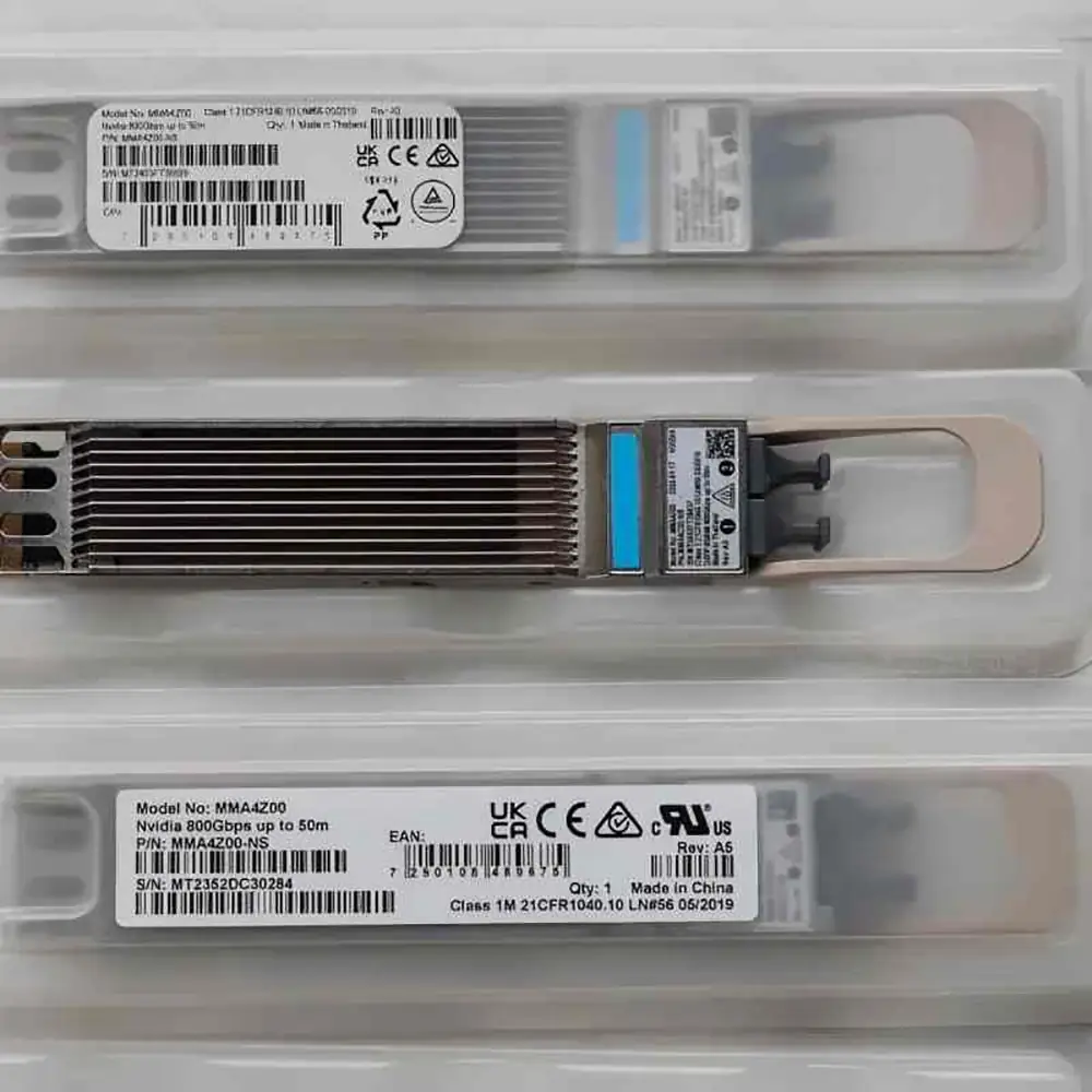
Twin-Port Design for Two 400G Connections
The module contains two independent 400G optical engines. This design supports two separate 400G connections through one OSFP module.
For network planners, the main advantage is the ability to organize two links within one module position. However, the two optical connections still require correctly matched cables and host-side configurations. Confirm the port mapping and cable arrangement before deployment.
Support for 200G Breakout Connections
The module can also work with supported 1:2 splitter fiber cables for 200G connections. This allows each 400G optical interface to be divided into two lower-speed links when the host equipment and network configuration support the arrangement.
Do not assume that any MPO breakout cable will work. Confirm the required channel mapping, polarity, connector configuration, and host breakout support before ordering.
OM3 and OM4 Distance Options
The specified maximum reach is 30m over OM3 and 50m over OM4. These limits help buyers assess whether existing multimode cabling can be reused.
Measure the complete cable route and check the fiber grade before selecting the connection method. If the installed route exceeds the supported distance, this module may not be suitable for that link.
Cooling and Host Device Considerations
The module is available in different OSFP cooling configurations for supported host platforms. NVIDIA documentation identifies finned-top versions for certain air-cooled switches and flat-top versions for specific systems with different cooling designs.
Buyers should verify the exact version required by the target device. Do not select a version based only on the OSFP form factor.
Ethernet and InfiniBand Applications
The module supports both Ethernet and InfiniBand applications within its qualified configurations. It can be considered for supported data center switching and high-performance computing connections.
Before deployment, check the host platform’s compatibility documentation and confirm the required protocol, port configuration, and cooling version.
Frequently Asked Questions
Can the MMA4Z00-NS provide a single 800G optical connection?
It uses a twin-port design with two independent 400G optical connections. Buyers should confirm the required port architecture and host configuration rather than treating it as a conventional single-port 800G module.
Can the MMA4Z00-NS support 200G connections?
Yes. It can support 200G breakout connections when used with compatible 1:2 splitter fiber cables and supported host configurations. Cable mapping and polarity must be checked before installation.
Which cooling version should I choose?
The correct version depends on the host device’s thermal design. Check the equipment documentation to determine whether a finned-top or flat-top OSFP module is required.
Can OM3 and OM4 fiber be used interchangeably?
Not without checking the supported distance. Both are multimode fiber types, but their bandwidth characteristics differ. The maximum reach must follow the transceiver’s specifications for each fiber grade.
Why does an optical link fail even when the connectors fit?
Possible causes include incorrect polarity, mismatched fiber types, contaminated connector end faces, excessive link loss, or unsupported host configurations. Check the complete optical path rather than focusing only on the connector fit.
Conclusion
Selecting an 800G module requires a complete view of the network connection. The transceiver, host equipment, fiber grade, connector assembly, and cooling design must work together. A specification comparison is only the starting point; installation compatibility and link testing determine whether the final connection is reliable.
When evaluating an optical module Manufacturer, buyers should also consider product traceability, specification consistency, compatibility support, and the availability of technical documentation. These factors help simplify replacement purchases and reduce uncertainty when expanding a data center network.
If you are sourcing 800G optical transceivers for AI data center or high-performance computing networks, send CREA DAS TECH your host device model, required protocol, fiber type, cable distance, and connector configuration to confirm compatibility and request a quotation.